Linux_SPI_DevelopmentGuide-04
4 模块使用范例
4.1 内核原生驱动范例
驱动文件在 drivers/spi/spidev.c,此驱动是 Linux 内核自带的一个 spidev 通用驱动。其中调用 spi_register_driver() 注册 SPI 驱动,方便使用者实现 SPI message 数据的读写。
static int __init spidev_init(void)
{
int status;
/* Claim our 256 reserved device numbers. Then register a class
* that will key udev/mdev to add/remove /dev nodes. Last, register
* the driver which manages those device numbers.
*/
BUILD_BUG_ON(N_SPI_MINORS > 256);
status = register_chrdev(SPIDEV_MAJOR, "spi", &spidev_fops);
if (status < 0)
return status;
spidev_class = class_create(THIS_MODULE, "spidev");
if (IS_ERR(spidev_class)) {
unregister_chrdev(SPIDEV_MAJOR, spidev_spi_driver.driver.name);
return PTR_ERR(spidev_class);
}
status = spi_register_driver(&spidev_spi_driver);
if (status < 0) {
class_destroy(spidev_class);
unregister_chrdev(SPIDEV_MAJOR, spidev_spi_driver.driver.name);
}
return status;
}
module_init(spidev_init);
static void __exit spidev_exit(void)
{
spi_unregister_driver(&spidev_spi_driver);
class_destroy(spidev_class);
unregister_chrdev(SPIDEV_MAJOR, spidev_spi_driver.driver.name);
}
module_exit(spidev_exit);
同时需要在对应的 spi 控制器的 dts 下加上 spi 子设备的设备信息描述,具体的配置信息如下所示:
&spi1 {
clock-frequency = <100000000>;
pinctrl-0 = <&spi1_pins_a &spi1_pins_b>;
pinctrl-1 = <&spi1_pins_c>;
pinctrl-names = "default", "sleep";
spi_slave_mode = <0>;
status = "disabled";
spi_board1@0 {
device_type = "spi_board1";
compatible = "rohm,dh2228fv";
spi-max-frequency = <0x5f5e100>;
reg = <0x0>;
spi-rx-bus-width = <0x4>;
spi-tx-bus-width = <0x4>;
status = "disabled";
};
};
对于 spi 控制器的描述在这里不再重复的陈述,这里的 spi_board1@0 就是我们虚拟的一个 spi 从设备,
• device_type :表示设备的类型;
• compatible :驱动匹配信息;
• spi-max-frequency :从设备的最大频率;
• reg :从设备的寄存器地址;
• spi-rx-bus-width:对从设备进行数据读取时使用的 data 数据线个数;
• spi-tx-bus-width :对从设备进行数据写入时使用的 data 数据线个数;
• status :从设备的状态;
在 menuconfig(Device Drivers->SPI support)里面配置上 User mode SPI device driver support 选项。
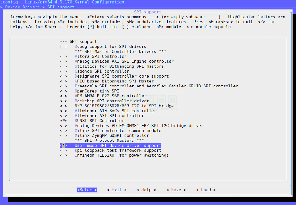
图 4-1: spidev
编译烧录固件之后会在小机文件系统的/dev 目录下发现 spidevX.0(X=0~2) 设备,可以对 spidevX.0 进行读写操作。或者使用 Linux 自带的 spi 工具:在 tina/lichee/linux-5.4/tools 目录下, 运行如下命令:
make spi
然后在 tina/lichee/linux-5.4/tools/spi/下会有 spidev_test 可执行文件,拷贝到小机根文件系统中,运行如下命令即可进行测试:
/spidev_test -D /dev/spidevX.0
4.2 Slave 模式驱动范例
需要在 board.dts 中相应的 SPI 节点设备配置 spi_slave_mode = <1>。
4.2.1 Slave 写数据
以 spidev1.0 设备为例,发送 0~9 十个数据:
#define DEVICE_NAME "/dev/spidev1.0"
#define HEAD_LEN 5
#define PKT_MAX_LEN 0x40
#define STATUS_LEN 0x01
#define SUNXI_OP_WRITE 0x01
#define SUNXI_OP_READ 0x03
#define STATUS_WRITABLE 0x02
#define STATUS_READABLE 0x04
#define WRITE_DELAY 200
#define READ_DELAY 100000
void dump_data(unsigned char *buf, unsigned int len)
{
unsigned int i;
unsigned char tmp[len*2], cnt = 0;
for (i = 0; i < len; i++) {
if (i%0x10== 0)
cnt += sprintf(tmp + cnt, "0x%08x: ", i);
cnt += sprintf(tmp + cnt, "%02x ", buf[i]);
if ( (i%0x10== 0x0f) || (i == (len -1)) ) {
printf("%s\n", tmp);
cnt = 0;
}
}
}
void batch_rand(char *buf, unsigned int length)
{
unsigned int i;
srand(time(0));
for(i = 0; i < length; i++) {
*(buf + i) = rand() % 256;
}
}
int main(int argc, const char *argv[])
{
unsigned int length = 0, test_len;
char wbuf_head[HEAD_LEN] = {SUNXI_OP_WRITE, 0x00, 0x00, 0x00, 0x00};
char rbuf_head[HEAD_LEN] = {SUNXI_OP_READ, 0x00, 0x00, 0x00, 0x00};
char wbuf[PKT_MAX_LEN], rbuf[PKT_MAX_LEN], i, time;
int fd, ret;
test_len = 10;//send 10 numbers
if (test_len > PKT_MAX_LEN) {
printf("invalid argument, numbers must less 64B\n");
return -1;
}
wbuf_head[4] = test_len;
rbuf_head[4] = test_len;
for (i = 0; i < test_len; i++)
wbuf[i] = i;
printf("wbuf:\n");
dump_data(wbuf, test_len);
fd = open(DEVICE_NAME, O_RDWR);
if (fd <= 0) {
printf("Fail to to open %s\n", DEVICE_NAME);
ret = -1;
return ret;
}
{//write
if (write(fd, wbuf_head, HEAD_LEN) != HEAD_LEN) {
printf("W Fail to write head\n");
ret = -1;
goto err;
} else
printf("W write head successful\n");
usleep(WRITE_DELAY);
if (write(fd, wbuf, test_len) != test_len) {
printf("W Fail to write data\n");
ret = -1;
goto err;
} else
printf("W write data successful\n");
usleep(READ_DELAY);
}
err:
if (fd > 0)
close(fd);
return ret;
}
4.2.2 Slave 读数据
以 spidev1.0 设备为例,读十个数据:
#define DEVICE_NAME "/dev/spidev1.0"
#define HEAD_LEN 5
#define PKT_MAX_LEN 0x40
#define STATUS_LEN 0x01
#define SUNXI_OP_WRITE 0x01
#define SUNXI_OP_READ 0x03
#define STATUS_WRITABLE 0x02
#define STATUS_READABLE 0x04
#define WRITE_DELAY 200
#define READ_DELAY 100000
void dump_data(unsigned char *buf, unsigned int len)
{
unsigned int i;
unsigned char tmp[len*2], cnt = 0;
for (i = 0; i < len; i++) {
if (i%0x10== 0)
cnt += sprintf(tmp + cnt, "0x%08x: ", i);
cnt += sprintf(tmp + cnt, "%02x ", buf[i]);
if ( (i%0x10== 0x0f) || (i == (len -1)) ) {
printf("%s\n", tmp);
cnt = 0;
}
}
}
void batch_rand(char *buf, unsigned int length)
{
unsigned int i;
srand(time(0));
for(i = 0; i < length; i++) {
*(buf + i) = rand() % 256;
}
}
int main(int argc, const char *argv[])
{
unsigned int length = 0, test_len;
char wbuf_head[HEAD_LEN] = {SUNXI_OP_WRITE, 0x00, 0x00, 0x00, 0x00};
char rbuf_head[HEAD_LEN] = {SUNXI_OP_READ, 0x00, 0x00, 0x00, 0x00};
char wbuf[PKT_MAX_LEN], rbuf[PKT_MAX_LEN], i, time;
int fd, ret;
test_len = 10;
if (test_len > PKT_MAX_LEN) {
printf("inval argument, numbers must less 64B\n");
return -1;
}
wbuf_head[4] = test_len;
rbuf_head[4] = test_len;
fd = open(DEVICE_NAME, O_RDWR);
if (fd <= 0) {
printf("Fail to to open %s\n", DEVICE_NAME);
ret = -1;
return ret;
}
{//read
if (write(fd, rbuf_head, HEAD_LEN) != HEAD_LEN) {
printf("R Fail to write head\n");
ret = -1;
goto err;
} else
printf("R write head successful\n");
usleep(READ_DELAY);
if (read(fd, rbuf, test_len) != test_len) {
printf("R Fail to read data\n");
ret = -1;
goto err;
} else
printf("R read data successful\n");
usleep(READ_DELAY);
}
printf("rbuf:\n");
dump_data(rbuf, test_len);
err:
if (fd > 0)
close(fd);
return ret;
}
4.2.3 Slave 使用 & 测试
4.2.3.1 环境搭建
4.2.3.1.1 硬件环境
本此测试使用两块开发板搭建环境,一块做 master,一块做 slave。
将 MASTER 与 SLAVE 的 SPI1 的 CS、CLK 按名字对应连接起来,MASTER 的 MOSI 接SLAVE 的 MOSI,MASTER 的 MISO 接 SLAVE 的 MISO,将两块开发板共地。
4.2.3.1.2 Menuconfig
打 开 menuconfig 的 CONFIG_SPI_SUNXI 与 CONFIG_SPI_SPIDEV,如下图所示。
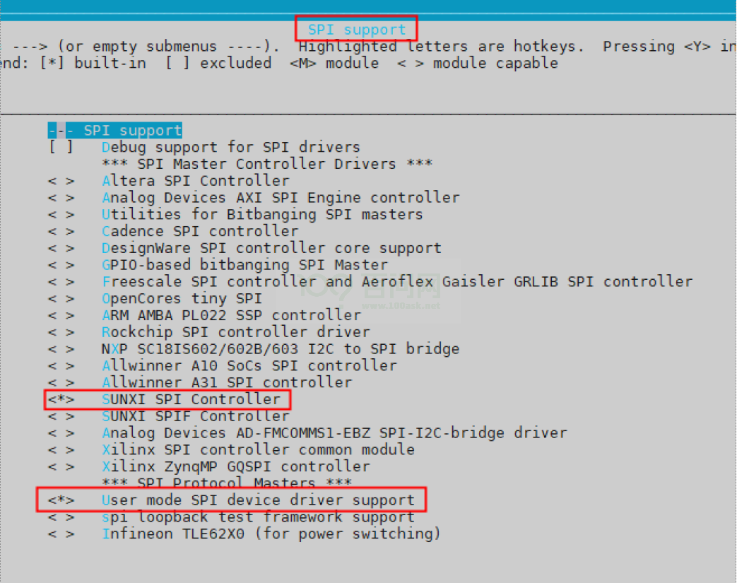
图 4-2: menuconfig
4.2.3.1.3 DTS
设备树路径:device/config/chips/xxx(t507)/configs/xxx(demo2.0)/board.dts,添加以下节点:
spi1: spi@05011000 {
pinctrl-0 = <&spi1_pins_a &spi1_pins_b>;
pinctrl-1 = <&spi1_pins_c>;
spi_slave_mode = <0>;
status = "okay";
spi_board1 {
device_type = "spi_board1";
compatible = "rohm,dh2228fv";
spi-max-frequency = <30000000>;
reg = <0x0>;
spi-rx-bus-width = <0x1>;
spi-tx-bus-width = <0x1>;
};
};
注:spi_slave_mode = <0> 为 Master 配置;spi_slave_mode = <1>,为 Slave 配置
4.2.3.2 测试
分别设置 Master 和 Salve 的 DTS,并编译出对应固件,烧写固件。
4.2.3.2.1 Slave
Slave 端执行下列命令,打开 Slave 的调试打印,这样可以看到读写的数据。
4.2.3.3 测试结果
Maset source data 和 target data 打印数据一致,即表明测试通过。
--------------------------------------------
				  n test
--------------------------------------------
W write head successful
W write data successful
source data:
0x00000000: 5a 5a 5a 5a 5a 5a 5a 5a 5a 5a 5a 5a 5a 5a 5a 5a
0x00000010: 5a 5a 5a 5a 5a 5a 5a 5a 5a 5a 5a 5a 5a 5a 5a 5a
R write head successful
R read data successful
target data:
0x00000000: 5a 5a 5a 5a 5a 5a 5a 5a 5a 5a 5a 5a 5a 5a 5a 5a
0x00000010: 5a 5a 5a 5a 5a 5a 5a 5a 5a 5a 5a 5a 5a 5a 5a 5a
slave function [PASS]
4.2.3.4 自定制说明
用户可以自定制从设备功能,要操作从设备,需要发送 5 个 byte 的操作请求,说明如下:
第 1 个 Byte:操作码
SUNXI_OP_WRITE 0x01
SUNXI_OP_READ 0x03
//读写是相对于master
第 2~4 个 Byte:地址(2 是高位地址)
第 5 给 Byte:长度(长度要求小于 64Byte)
4.2.3.4.1 操作码添加
现在我们只支持读写操作,用户自行拓展,在drivers/spi/spi-sunxi.c 的sunxi_spi_slave_handle_head函数中添加命令对应的操作函数
if (head->op_code == SUNXI_OP_WRITE) {
	sunxi_spi_slave_cpu_rx_config(sspi);
} else if (head->op_code == SUNXI_OP_READ) {
	sunxi_spi_slave_cpu_tx_config(sspi);
} else {
    dprintk(DEBUG_INFO, "[spi%d] pkt head opcode err\n", sspi->master->bus_num);
    ret = -1;
    goto err1;
}
4.2.3.4.2 地址及缓存
第 2~4 个 Byte 的地址是用于指定读写缓存数据,缓存大小宏在drivers/spi/spi-slave-protocol.h中定义,用户自行设置,单位 Byte
#define STORAGE_SIZE 128
4.2.3.4.3 长度
每次读写数据长度要求小于 64Byte,由于 SPI RX/TX 的 FIFO 缓存大小为 64Byte,为了防止读写时有一端设备没有及时拿走数据导致 buf 溢出,一次传输要求长度小于 64Byte,如果要读写大于 64Byte 数据,可分多次进行传输,地址偏移好就没问题。